Introduction
This page serves to detail the control methods and overall workings of developing a platform that can automatically level itself using a STM32 Nucleo L476. The system is composed of a touch panel to track the ball's position and velocity, an IMU BNO055 to track the platform's orientation, and two DC motors that can alter the orientation of platform.
As discussed in more detail in the section below, cascade control with two closed loops was used to accomplish sufficient balancing. The program is composed of various task files that are executed sequentially using cooperative multitasking. Each task file runs at a different frequency depending on the importance of its data collection to balance the ball. Within each closed loop, the user can decide which gains (proportional, derivative, or integral) to set. Aside from the gain values set, the IMU was modified with an angle offset to more easily center the bal, and the duty cycle of each motor was limited to prevent any excessive reactions to the ball's position. Within the class used to interact with the touch panel, we also implement alpha-beta filtering to decrease noise of each reading for our calculaiton of the balls position and velocity.
A video demonstration of the ball balancing platform can be found in the link below. Data was collected and is discussed in the results section.
Video demonstration: https://vimeo.com/689894177
See the link below for the code respository to this lab. Code repository for this lab: https://bitbucket.org/rdeanr/me305/src/master/Lab5/
Closed Loop Control
This program implements closed loop control using proportional and derivative gains. Using a reference angle of 0 degrees, the the loop then calculates a duty cycle. This duty cycle is then sent to the motors that operate under pulse width modulation. See closedloop.ClosedLoop for more information on how the class functions.
User Task
Implemented as a finite state machine, this file handles all user inputs and sets flags or shares variables that can interact with all other tasks. The state transition diagram can be seen below. See task_user.py for more information.

IMU Task
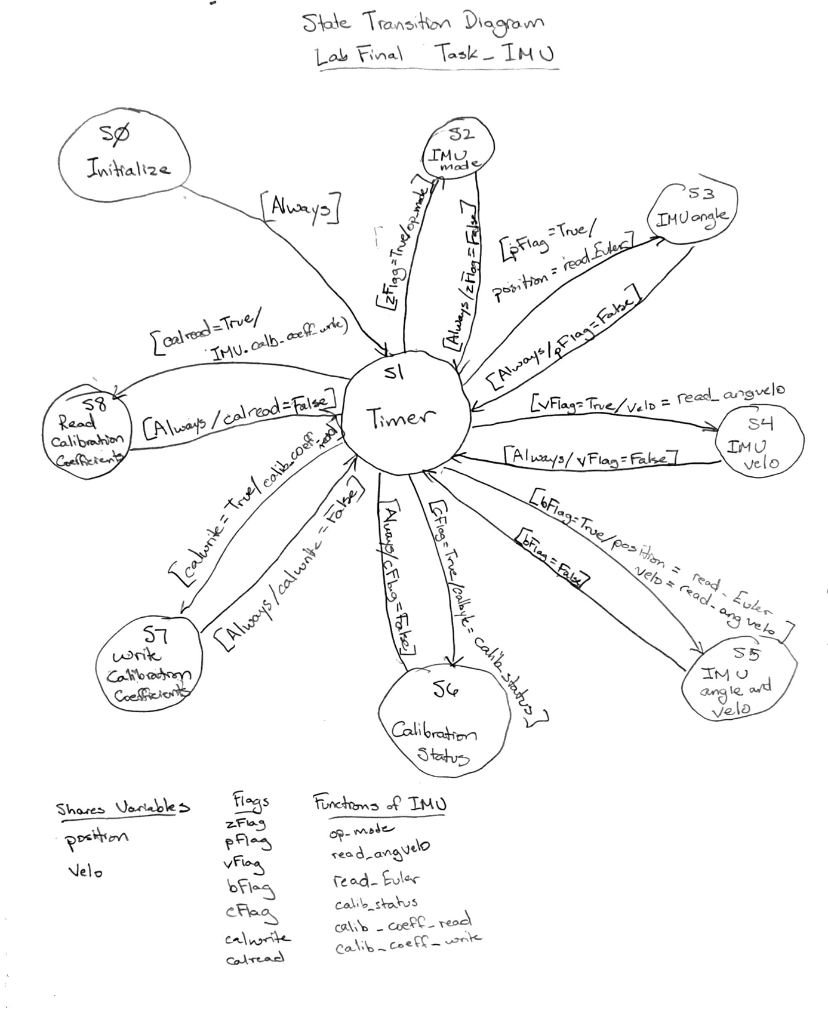
This task directly interfaces with the IMU BNO055 to collect platform position and angular velocity data. It is also used to calibrate the IMU and sends commands to BNO_driver.BNO055 to write and read calibration coefficients to and from a text file. A state transition diagram can be seen in the image below.

Motor Task
This task directly interacts with the motors and then alters flag values to be sent back to the user task and interpretted. Receiving input from the user task, it directly controls the duty cycle of each motor. The state transition diagram can be seen below.

Task Diagram
This diagram shows the interaction between the task files and which values are shared between them.
